Blueprint Automated Door Tutorial
Contents
Overview
In this first series of Blueprint tutorials, we take a look at how to modularly tackle a basic level designer function - an automated door.

All chapters of this tutorial are designed to build upon one another. In order to complete Chapter 4, for example, you need to have completed Chapters 1, 2, and 3.
Assets
For the purposes of this tutorial, we will be using the Blueprint Third Person project.
This tutorial also makes use of a few static meshes, materials, and textures. These are all available within this zip file:
UPDATE: The Door.zip file linked above has a few material assets missing. You may download the following zip file ( https://www.dropbox.com/s/194bbfyp4x87es8/Door_FulllAssets.zip?dl=0 ) which contains the missing materials as well as the completed blueprints. This has been tested on the latest UE4 release i.e. UE v 4.12.5.
Once you've downloaded the zip file, open up the Project Folder of the Blueprint Third Person project you've created and extract the contents into the folder.
Target Audience
As this is a base-level introduction, very little is assumed of the user's experience. Ideally, you should already be familiar with the basic controls of UE4 and comfortable navigating through the Content Browser. It will also help if you are familiar with the concept of Blueprints. More information can be found within the following documents:
- Engine/Blueprints/GettingStarted
- Engine/Blueprints/Editor
- Engine/Blueprints/UserGuide
Target Blueprint Features
As with all Blueprints, it will be important to know in advance what it is you want to achieve as your final effect. In our case, we want an level designer to be able to drop this door Blueprint into a level, and it should just work. Players should be able to approach it and it should automatically open. Later, we would like to implement various features to enhance the overall usefulness of our Blueprint asset. Some of these will be for direct and obvious functionality enhancements, while others are purely academic - designed to show off features and workflow aspects to the Blueprint system.
These features include:
- Initial Setup : Ability to drag & drop as many doors into a level as we need, and for them to provide basic functionality with no further required setup.
- Scale Controls : Ability to adjust uniform scale as a global variable.
- Overrides : Ability to swap out the meshes and materials for the door, but starting with a default for rapid setup.
- Organizing and Commenting : Clear node organization and commenting.
- Making a Usable Door : Ability to establish if the door opens when approached or needs to be "used" with player input.
- Creating a Door Counter : Ability to establish an optional "transaction counter" Blueprint that tracks total times any door opens. This will be a separate Blueprint that must have the ability to communicate with any and all door Blueprints placed in the level.
Initial Setup
This first series of tutorials offers an introductory view to the world of working with Blueprints. Throughout this example, you will be creating a modular automated door in the most basic sense, including the following features:
- A pair of static meshes (a "door frame" and a "doorway", the latter being the part that moves).
- A Box Component which will serve as a trigger volume for proximity calculation. The trigger volume is nothing more than a 3d space that is "triggered" when the player enters it. We can hook up actions to these triggers -- like opening a door!
- A Blueprint node network which will drive animation of the door.
In later tutorials, we will augment this system so that users can swap out the meshes used for the door and the door frame, override materials, and much more.
New Blueprint
1. Within the Content Browser, create a new folder with the name of your choice. Select this folder so that your new Blueprints will be placed within it.
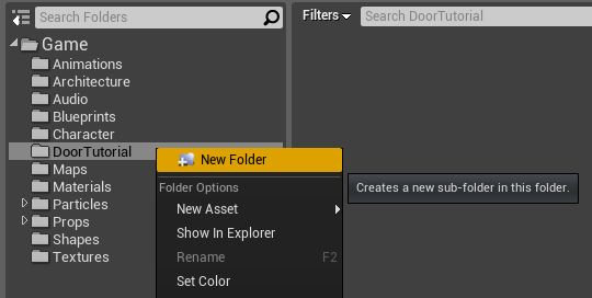
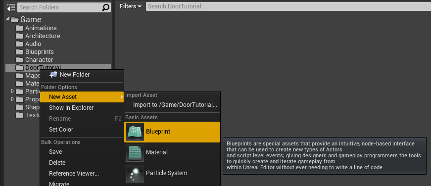
2. Right-click in the Content Browser and choose Blueprint Class.
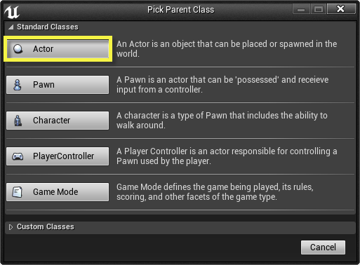
3. The Pick Parent Class window will appear. Expand
Object
and select
Actor
. This means you are creating a placeable Blueprint Actor. Click the
Ok
Button.
4. For the Blueprint's name, choose
Tutorial Door
. Press Enter. This creates a new blank Blueprint ready for construction.
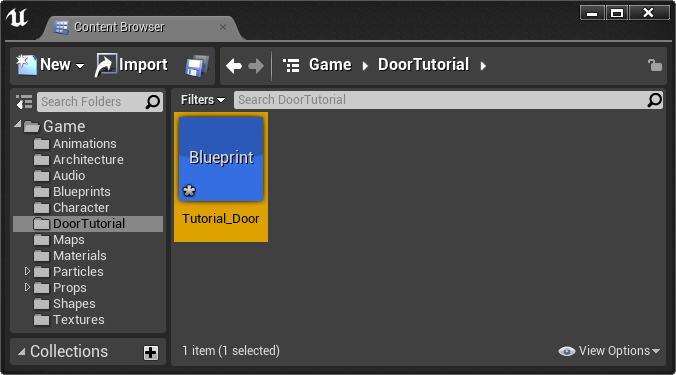
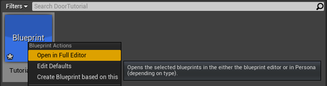
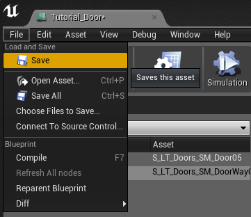
5. One of the most critical steps when working with Blueprints is to save your work often. There are a few ways to do this. For our purposes, we will use the
Save
Button in the Content Browser. Click this now.
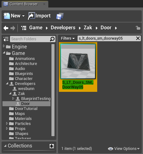
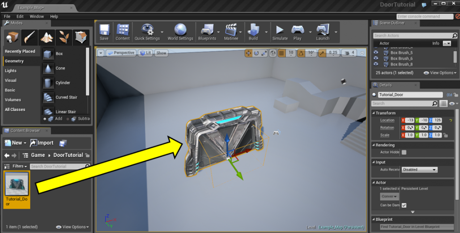
You can always verify when a Blueprint requires saving by looking at its icon in the Content Browser. In the lower left corner of the icon, you will see a small silver asterisk for any asset you should save. This asterisk can be seen in the image above, and will disappear once the most recent changes to a Blueprint have been saved.
Mesh Components
1. Right-click Tutorial Door and choose Edit . This will open the Blueprint Editor.
2. Notice the Components tab on the left side of the editor. If this tab is not visible or is closed, it can be recovered
by selecting the Window drop down menu and selecting Components.
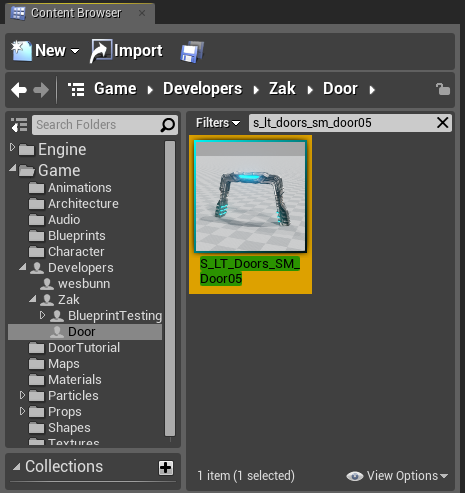
3. In the Content Browser, locate the
S_LT_Doors_SM_Door05
static mesh.
(a copy of this asset is contained within the
assets for these tutorials
for convenience)
4. Click Add Component.
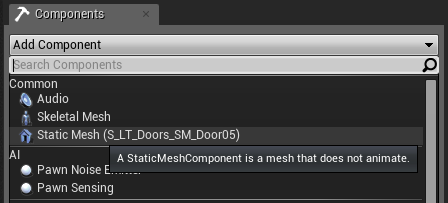
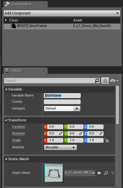
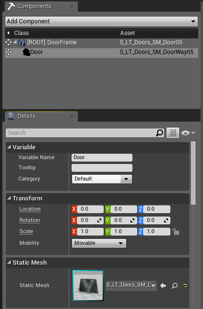
5. Select the new
Unnamed StaticMeshComponent
. In the Details panel, set the Variable name to
DoorFrame
.
6. In the Content Browser, locate the
S_LT_Doors_SM_DoorWay05
static mesh.
(a copy of this asset is contained within the
assets for these tutorials
for convenience).
7. Click the Component list again and choose Selected Asset at the top. Click Add Component, then set the variable name for the new static mesh component to
Door
.
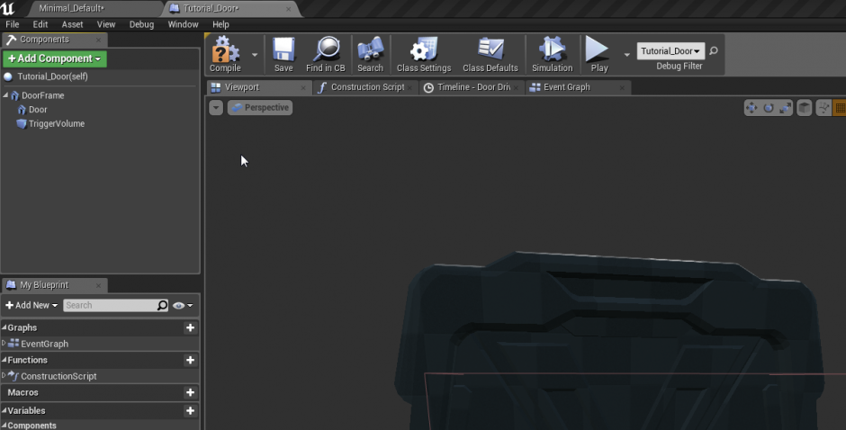
8. In the Component Viewport, you should now see the door and the doorway mesh.
8. Save your Blueprint by choosing File > Save in the Blueprint Editor. Ctrl + S can also be used to save all files in the project.
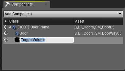
Box Component
1. Make sure you're looking at the ComponentList.
2. From the Add Component dropdown, choose Box Collision . Set the Variable name to TriggerVolume .
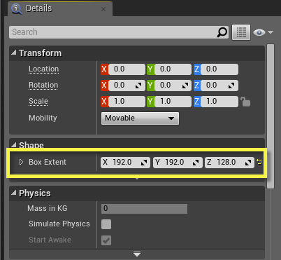
3. With the
TriggerVolume
Box Collision Component selected, look at the Details panel. In the Shape category, set
Box Extent
to <192, 192, 128>.
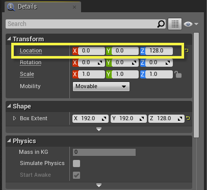
4. Scroll up to the Transform section of the Details panel and set
Location
to <0, 0, 128>.
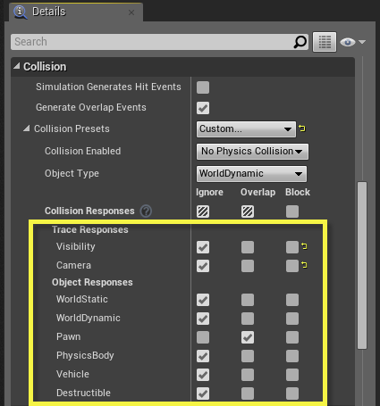
5. Scroll down to the Collision group, and change the Collision Presets to Custom . When you do this, the rest of the Collision group items will change, giving you the ability to check the box immediately under Ignore . You'll also see an item called Pawn . Recall that a Pawn is anything that can be controlled by the player. Since we want the collision to be triggered when the player's collision boundary overlaps this, we'll check the Overlap checkbox for Pawn.
This means that when the pawn touches this component, it will register an overlap contact, rather than being blocked altogether.
6. Compile by clicking "Compile" or hitting
F7
, then save your Blueprint.
Great! You just created a collision boundary and are ready to test out your new door.
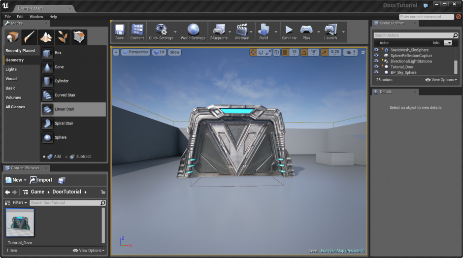
Level Testing
1. Open the Content Browser and locate Tutorial_Door .
2. Drag and drop Tutorial_Door into your level.
3. Save your level and your Blueprint.
Initial Event
We will now begin setting up the system by which the door will move. In previous versions of the engine, this would be handled via a Matinee sequence. However, such a setup required that one modify keyframes to change door behavior. Here, we will set up start and end points for the door and linearly interpolate between them.
1. Open the
Tutorial_Door
Blueprint in the Blueprint Editor.
2. Click the Script button and select the Event Graph tab to show the Event Graph.
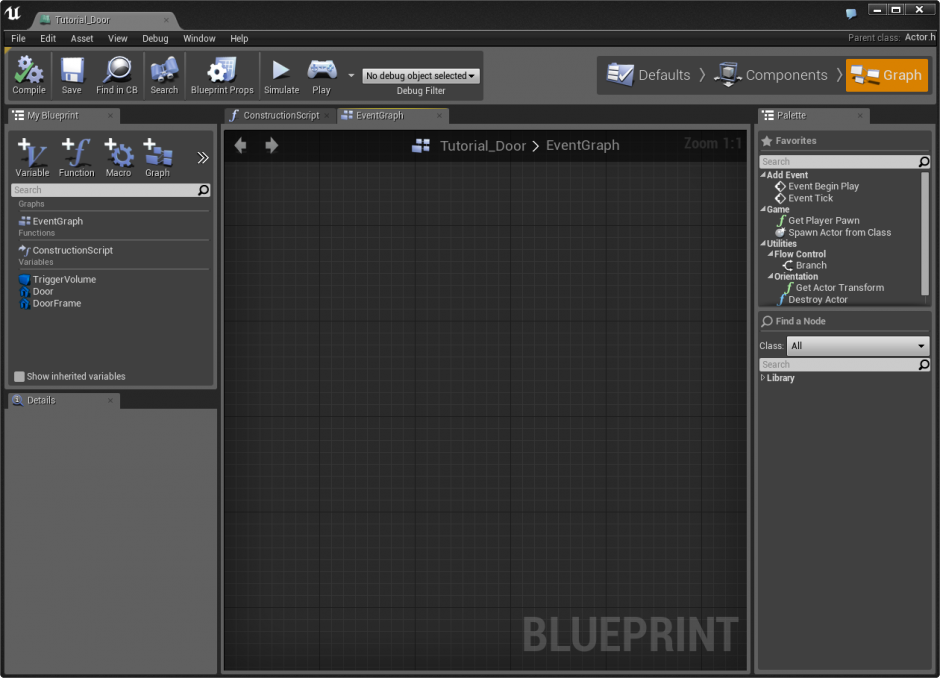
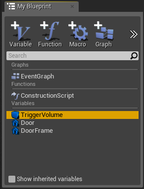
3. In the
My Blueprint
tab, select the Trigger Volume variable.
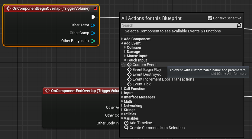
4. Right-click in the Blueprint Event Graph. Start typing "ComponentBeginOverlap." You will see
OnComponentBeginOverlap
appear in the list. Click it to create a new ReceiveComponentTouch event.
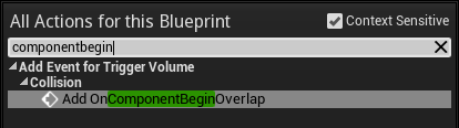
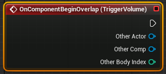
This event is fired whenever another actor touches the Blueprint actor. Since the box component only calculates touches from the pawn, this means that the event will be fired as a pawn (the player in this case) passes into the box component. This causes the box component to behave like a trigger volume.
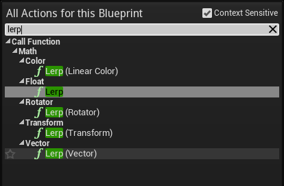
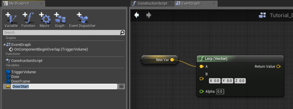
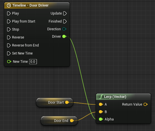
5. We will now set up the linear interpolation (lerp) system. However, note that until we create some sort of driving force, our lerp will not actually produce any motion. Right-click and type "lerp" in the search line. From the filtered selections, choose Lerp (vector) .
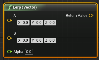
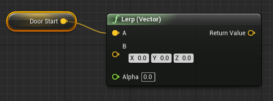
6. On the
Lerp (Vector)
node, right-click on the
A
input vector plug and choose
Promote to Variable
. Name the variable
DoorStart
.
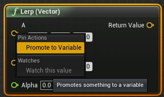
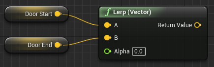
7. Right-click on the
B
input vector plug and choose
Promote to Variable.
Name this variable
DoorEnd
.
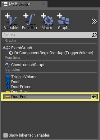
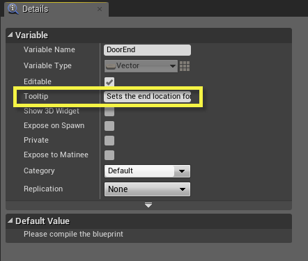
8. In the My Blueprint tab on the upper right side of the Blueprint Editor, select the Door End variable and click the Public Variable button. It will turn to an open eye and appear yellow, indicating that the variable is public, but requires a tooltip.
9. Select the
Door End
variable in the
My Blueprint
panel. In the
Details
panel, check the
Show 3D Widget
option. In the
Category
field, enter "Door Setup." Also, add a tooltip. Something like, "Sets the end location for the motion of the door."
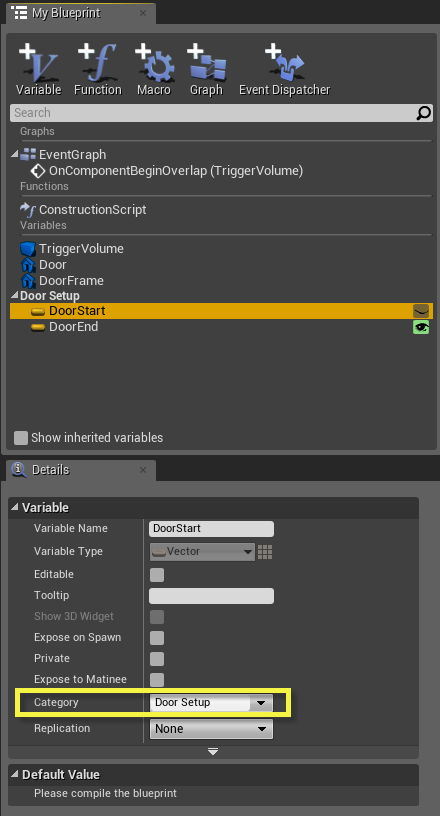
10. Select the
DoorStart
variable and enter "Door Setup" for the
Category
in the
Details
panel. This will cause DoorStart and DoorEnd to be placed under the DoorSetup category. Compile.
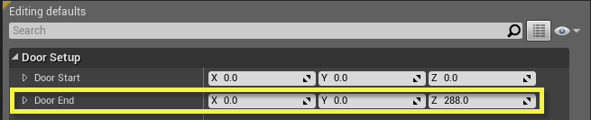
11. At the top of the Blueprint Editor, click the Defaults button. Set the Z value of
Door End
to
288
.
12. Compile and save your Blueprint.
Timeline Setup
We have everything in place to have a working door. We just need to set the driving system that will cause the door to animate. Think of this like adding a motor to the door. In this case, we will use a Timeline, which allows for the creation of simple interpolation calculations between keyframes.
See Timelines documentation for more details.
1. Open the Tutorial_Door Blueprint in the Blueprint Editor.
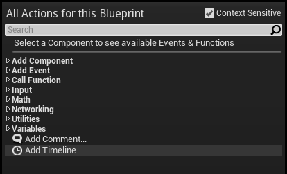
2. Within the Blueprint Editor Event Graph, right-click and choose Add Timeline...
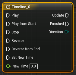
3. Set the name to "Timeline - Door Driver". Press Enter.
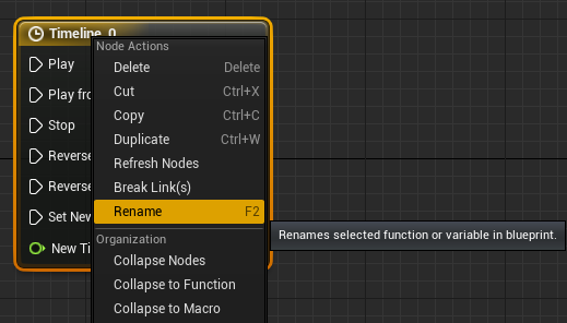
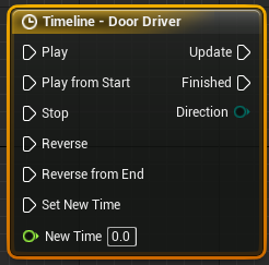
Timelines are serialized when created, meaning the name will generally be "Timeline_X" with X representing some number. By renaming your Timelines, it will be much clearer what each one is intended to do.
When you first rename the Timeline, you may see an Error on it. Simply recompile and it should disappear.
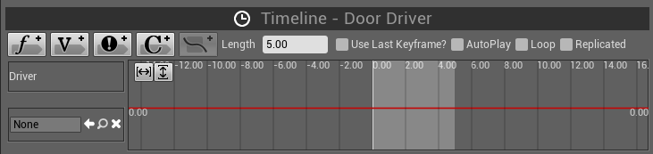
4. Double-click the Timeline node to open a Timeline Editor tab.

5. Click the
Add Float Track
Button. Set the Track Name to "Driver."
6. Within the Timeline curve window to the right,
Shift-click
on the default curve somewhere near the (0,0) coordinate. It does not have to be precisely at that location. This will create a keyframe along the timeline.
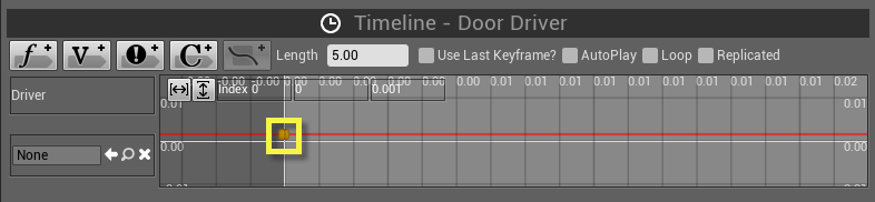
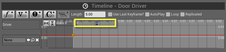
7. Select the new keyframe by clicking it. You will see two numeric input fields at the top of the window. The one on the left sets the time index of the keyframe, the one on the right sets the value. Set both of these inputs to 0.0, defining a relative translation of 0.0 at the beginning of the timeline.
8. Use Shift-click to create a second keyframe. Select the new keyframe and set the time field to 1.5 seconds and the value field to 1.0.
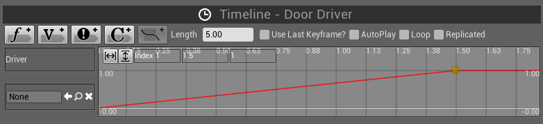
In order to see the curve in its entirety, you may need to click the
Zoom to Fit
buttons, located in the upper left of the Timeline graph!
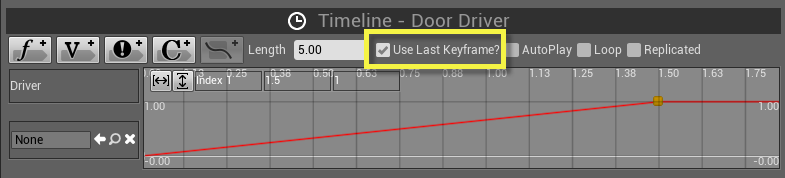
9. Before leaving the Timeline Editor, make sure to check the Use Last Keyframe? checkbox. This will keep the Timeline from calculating beyond the end of the final keyframe, which would give you several seconds of dead animation after the door had opened.
10. Return to the Event Graph and connect the
Driver
output of the Timeline to the Alpha input of the Lerp (vector) node.
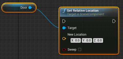
11. We now need to set up the node that will move the door. Select the Door component variable in the My Blueprint panel. Then right click in the graph and type "set Relative Location." This will create the node with the Door variable attached.
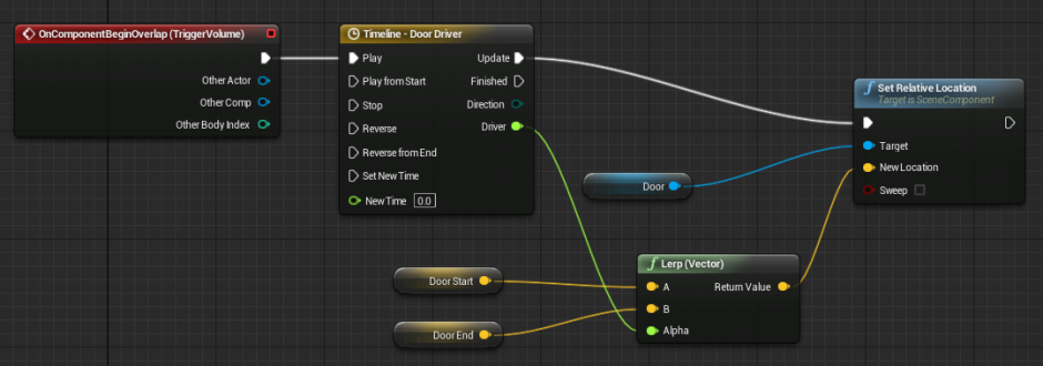
12. Finally, it's time to hook up our event, which should initiate Timeline playback and thereby open our door. Connect the output pin of the
OnComponentBeginOverlap
event to the Play input on the
Timeline - Door Driver
. Then connect the Timeline's
Update
pin to the execution input of the Set Relative Location. Finally, connect the
Return Value
of the Lerp (Vector) node to the
New Location
input on the Set Relative Location node.
13. Compile and Save your Blueprint.
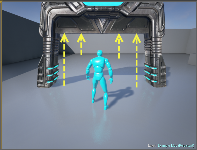
Testing and Debugging
In this tutorial we take a moment to drop our Blueprint into a level and give it a test. At this point, your doorway should be opening when the player approaches it. One of the great benefits of Blueprints of this sort is that we can easily test them out at any time by simply dropping the Blueprint actor into a level and then using Play In Editor to see how they're working.
Blueprints are error-checked every time they are compiled. If there are any errors within the node network, a window will appear in which all such errors are listed, along with links to jump you directly to the problem.
1. Open the Tutorial_Door Blueprint in the Blueprint Editor.
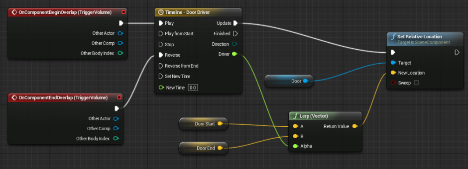
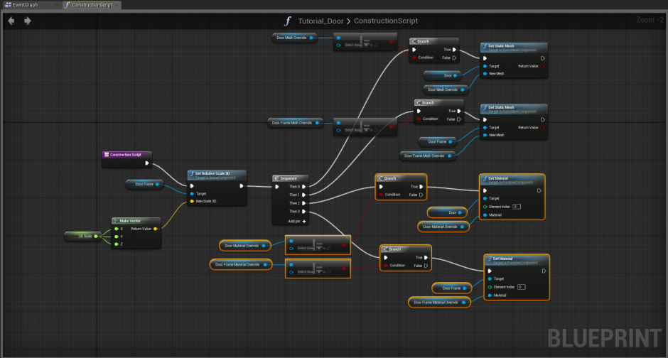
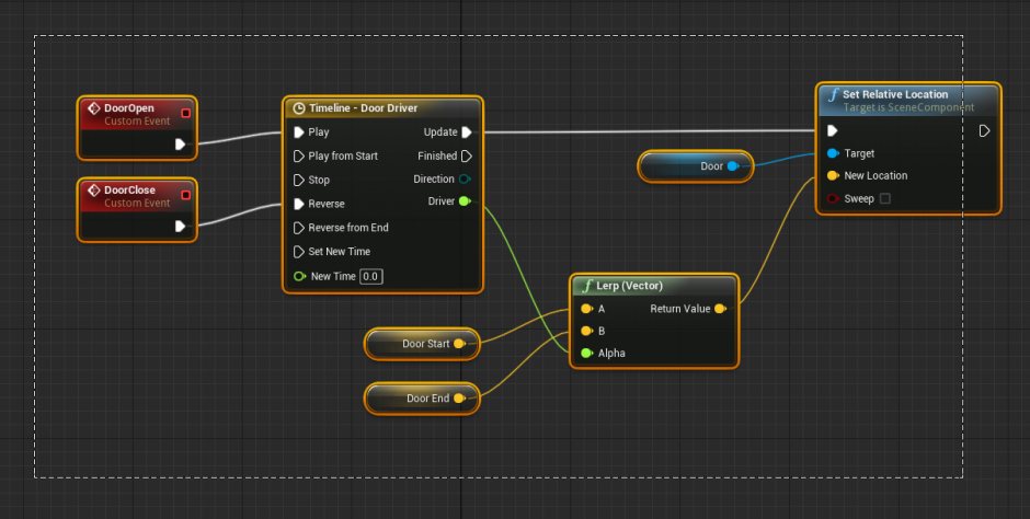
2. Be sure that the Blueprint has been fully compiled (press F7) in the Blueprint Editor. Should there be any errors that appear, click on the hyperlink within the error entry. The error itself should spell out the nature of the problem. Your network should look something like this:

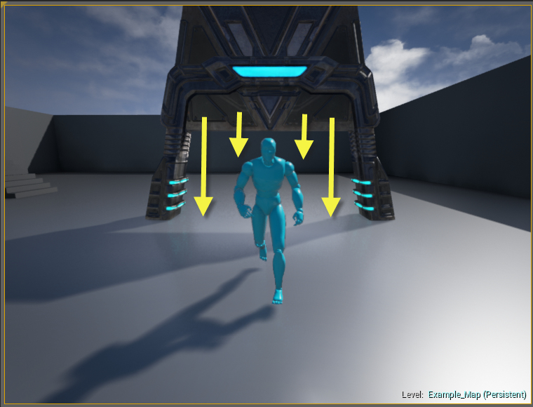
3. The Blueprint should be functional at this point. With the Blueprint placed in the level, press the Play in Editor button. When the player walks into the volume of the Box Component, the door should open.
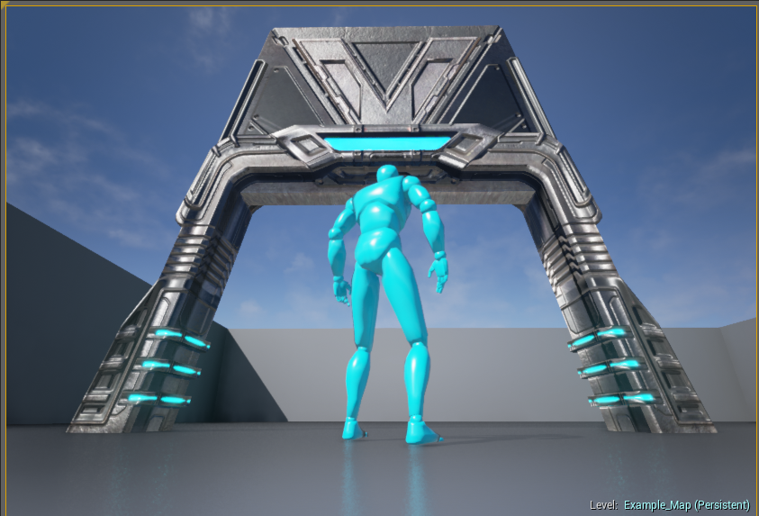
4. Save your level.
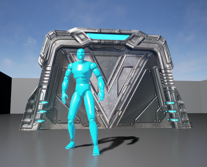
Closing the Door
When testing the level, you might have noticed that the door opens but does not close. In this tutorial, we will set up a counter event that causes the door to close when the player exits the volume of the BoxComponent.
1. Open the Tutorial_Door Blueprint in the Blueprint Editor.
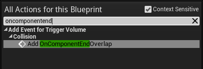
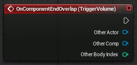
2. Select the Trigger Volume component variable. Right click near the Timeline and type "OnComponentEnd," which will bring up the OnComponentEndOverlap event. This event is fired whenever an object exits the BoxComponent.
3. Connect the output execution plug of the OnComponentEndOverlap event to the Reverse input of the Timeline. This will cause the Timeline to play backwards when the BoxComponent volume is exited, thereby closing the door.
4. Compile your Blueprint by pressing the Compile button and test the level. Your door should now open and close.
Adjusting Motion
In this tutorial, we will adjust the animation curve of the door's motion, causing it to start by moving quickly upward, but slowing to a stop. Because we are playing the same motion back to close the door, we the door will accelerate as it comes back down.
1. Open the Tutorial_Door Blueprint in the Blueprint Editor.
2. Within the Blueprint Editor, double-click the Timeline node to open it in the Timeline Editor.

3. Select the first keyframe by clicking it. Right-click on the keyframe and choose User. This will add user-controlled tangent handles to the keyframe so that you can adjust its shape.
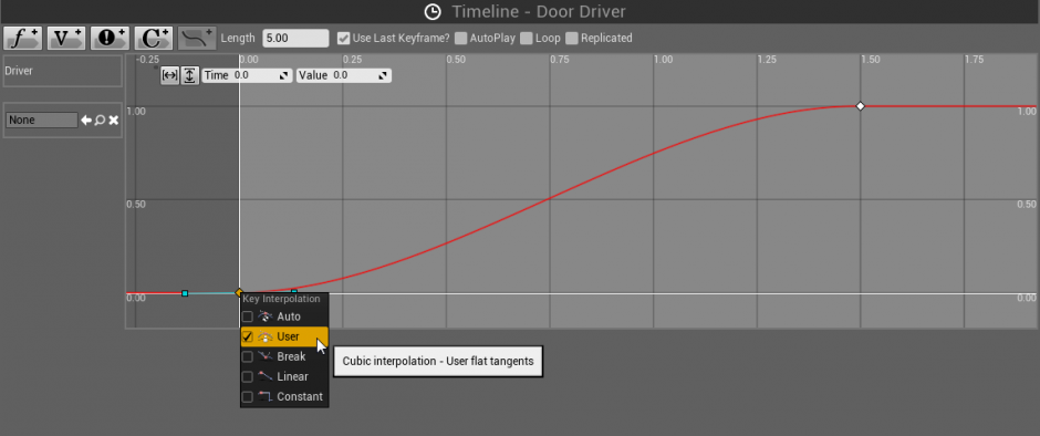
4. Repeat this process with the second keyframe, so that they are both set to User.
5. Move the inner tangent handles (the right for the first keyframe, left for the second) up slightly to shape the curve into an upward ramp that planes off at the end.
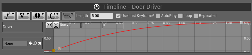
6. Compile and test. The door should start opening very quickly, slowing as it ascends. When closing, it starts slow and accelerates as it descends.
7. Save your Blueprint.
Chapter 1: Troubleshooting
| Problem | Solution |
|---|---|
| Cannot enter the BoxComponent volume. It seems to be solid. |
Select the BoxComponent within the Components tab. In the Details panel, make sure that under Collision that PawnMovement is set to Overlap and everything else is set to Ignore . |
| The OnComponentBeginOverlap event seems to be working, but the door is not moving. |
Verify the keyframes within the Timeline run between values of 0 to 1 over 1.5 seconds.
You can press the Zoom to Fit Horizontal and Zoom to Fit Vertical buttons to make sure that the curve is shaped properly. |
| The Timeline looks great. Door still isn't moving! |
Make sure the DoorEnd variable is set up properly.
If you didn't set its Default Value (we used 288), then you're probably trying to interpolate between 0 and 0 for start and end, respectively. |
| The door seems to vanish or fly away when I enter the BoxComponent. |
Make sure you're using a SetRelativeTranslation node instead of an AddRelativeTranslation node.
The two nodes look very much alike! Using an additive node will constantly add the translation value to the location of the door each time the Timeline updates. This causes the door to accelerate away, fast enough that it will seem to disappear. |
Scale Controls
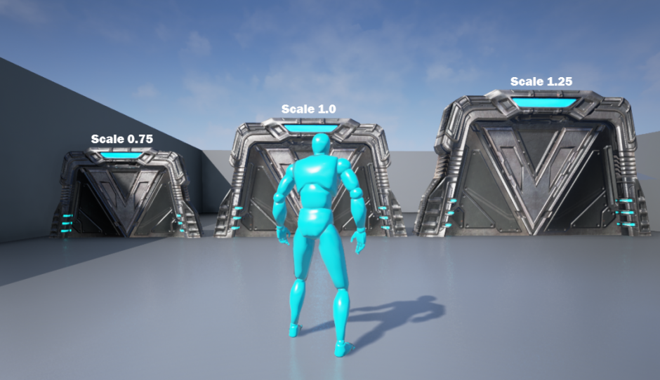
Now that the door itself is set up, it is time for us to start adding some convenience features to turn it into a useful and practical asset. The first of these will be a slider-based scale control system, which will allow a level designer to quickly increase or decrease the scale of the door. This slider will be accessible from the Details panel on any instance of the Blueprint that gets placed in the level.
Adding a Scale Control
In this tutorial we will implement a 3D scale adjustment system for our automated door. As you may have noticed, scaling the Blueprint itself does not have any effect. Instead, we will create a single slider control that can be used to quickly size the door up and down, starting from a base default value.
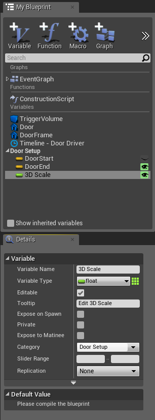
1. First, we need a new variable to hold the scale for the door. In the My Blueprint panel on the left, click the
New Variable
button. Set the type to Float, set the name to
3D Scale
, and set the remaining properties as shown below:
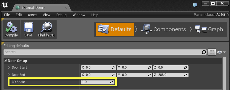
2. Click the
Defaults
button and set the default value of the
3D Scale
variable to 1.0.
3. Compile and save your Blueprint. At this time, there is nothing we can test just yet.
Finalizing Scale Control
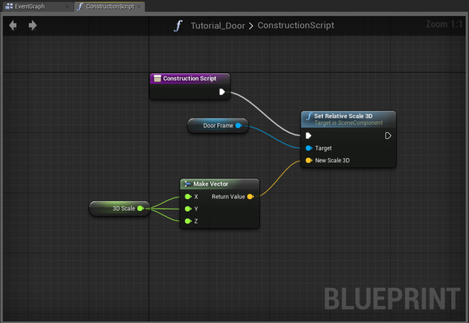
Now that we have our 3D Scale variable established, we will now implement it via the Blueprint's Construction Script. The Construction Script is executed when the Blueprint is first created in the world, and updated whenever any part of the Blueprint is updated during level construction.
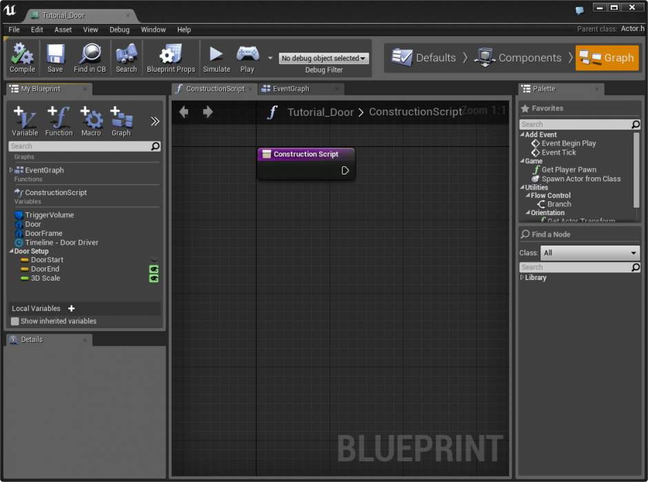
1. Double-click the Blueprint to open it in the Blueprint Editor and make sure that it has been added to the level for testing.
2. Within the Blueprint Editor, click the ConstructionScript tab at the top of the screen. This shows the Construction Script for this Blueprint, which currently just shows the Construction Script node. Think of this like an event that is called when the Blueprint is first created, or whenever it becomes edited during level design.
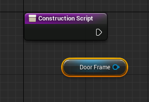
3. Select the My Blueprint tab on the left, then Ctrl-drag a copy of the
Door Frame
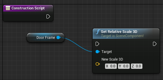
component variable into the Construction Script.
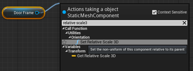
4. Drag a wire off the Door Frame node and release the mouse in open space. Type Set Relative Scale 3D and create a Set Relative Scale 3D node.
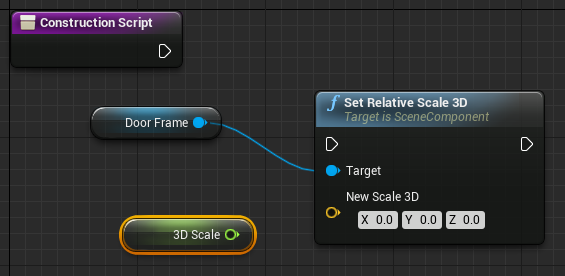
5. Ctrl-drag in a copy of the 3D Scale variable.
6. Right-click and create a Make Vector node.
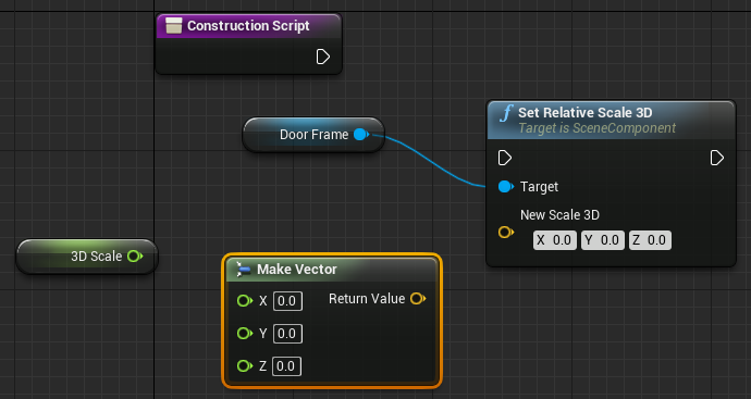
7. Connect the output of the 3D Scale node to all three inputs of the Make Vector node, then connect the output to the New 3D Scale input of the Set Relative Scale 3D node.
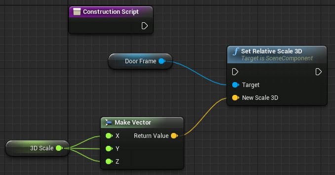
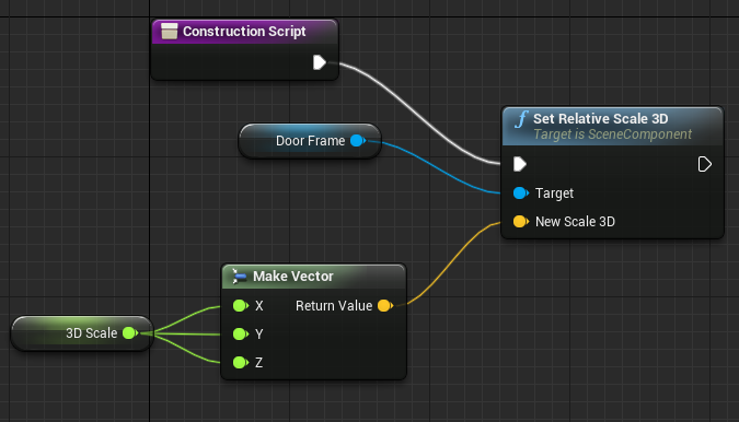
8. Finally, connect the output of the ConstructionScript node to the execution input of the Set Relative Scale 3D node.
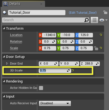
9. Compile and save your Blueprint.
10. In the main editor, watch your Blueprint in the viewport as you adjust the 3D Scale variable's slider from within the Details panel.
Chapter 2: Troubleshooting
| Problem | Solution |
|---|---|
| I cannot see the scaling slider in the Details panel. |
Make sure that the DoorScale variable is set to Editable (click the small eye icon). |
| After implementing the scale controls, the door seems to have vanished! |
Double-check the default setting for the DoorScale variable within the Blueprint Editor's Blueprint Defaults panel. It is likely that this was left at 0.0, which would size your door down to nothingness. |
Overrides
In this chapter we take a look at making our door Blueprint asset even more useful by adding the ability to override the static meshes and materials in use. Basically, we want the level designer to have the power to use any kind of vertically-opening door, starting with this Blueprint as a template. To do this, we will have to make use of the User Construction Script, which is run in advance of gameplay. Through this method, we can expose the ability for the LD to choose other meshes and materials from the Content Browser and use them to replace the assets set up by default.
This example is designed to make use of standard Materials, not Material Instance Constants. However, the text does include some guides to help make the minor modifications required to utilize Material Instances in your assets.
Mesh Overrides
In this tutorial we will adjust our automated door so that a level designer could quickly swap out the meshes for the door and the door frame. Since the Blueprint already has meshes in place for those parts, those existing meshes will be considered defaults. This is useful because an level designer can quickly lay out the doors wherever they are needed, but then quickly swap out meshes later down the road. It also opens the door for collaborative efforts, since a level layout artist can just drop the doors into place while a finishing artist comes in later and changes out the doors for something more appropriate.
1. Open the Blueprint's Construction Script.
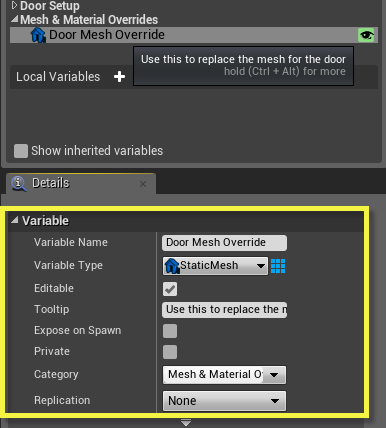
2. In the
My Blueprint
panel, click the
Add Variable
button to create a new variable. Select the new variable and in the
Details
panel set its type to
Static Mesh
and its name to
Door Mesh Override
. Set its remaining properties as shown below:
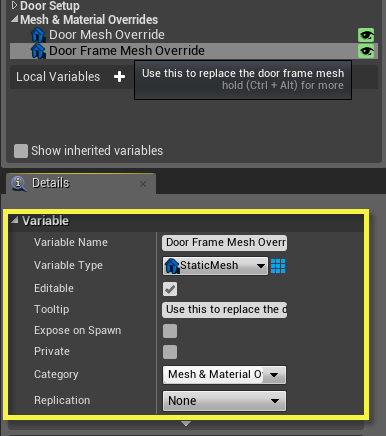
3. Create a second
Static Mesh
variable named Door Frame Mesh Override. Set its remaining properties as shown below:
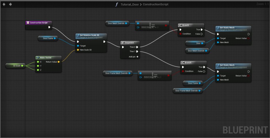
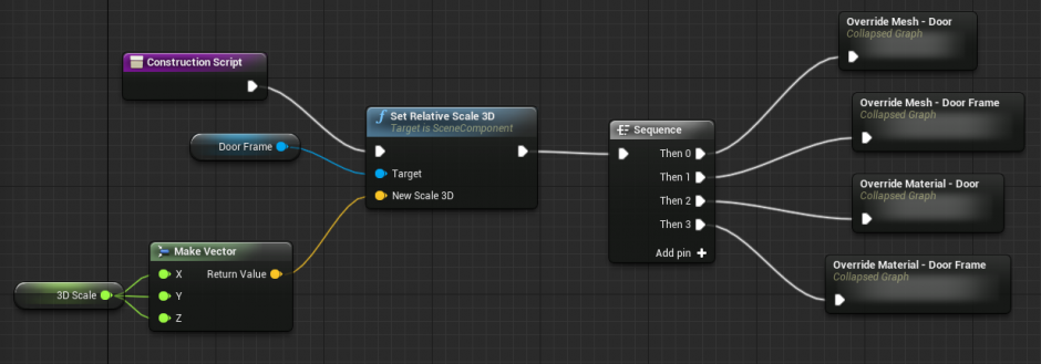
4. To the right of the Set Relative Scale 3D node, add a Sequence node. This will fire off a series of operations, one after another. Go ahead and connect it to the Set Relative Scale 3D node.
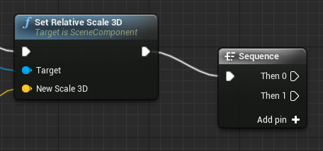
You may, for now, right-click on the
Then 2
and
Then 3
options and choose "Remove execution pin," since we will not be using those pins in this tutorial.
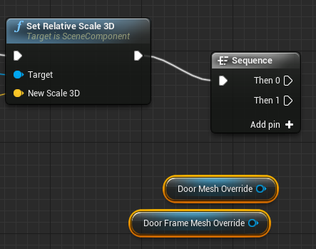
5. Ctrl-drag in a copy of the Door Mesh Override variable, and also a copy of the Door Frame Mesh Override variable.
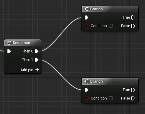
6. The first thing we will need to do is make sure that these variables are not empty. If either of them are, then we need not swap out that mesh. Create 2 Branch nodes and connect them to the Then 0 and Then 1 output pins of the Sequence node.
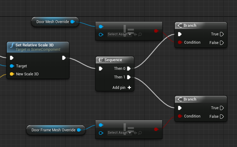
7. Drag a wire from the DoorMeshOverride variable and type "Not equal" to create a
Not Equal (Object)
node. Connect the output pin to the Condition pin on the Branch node. Repeat for the
Door Frame Mesh Override
variable.
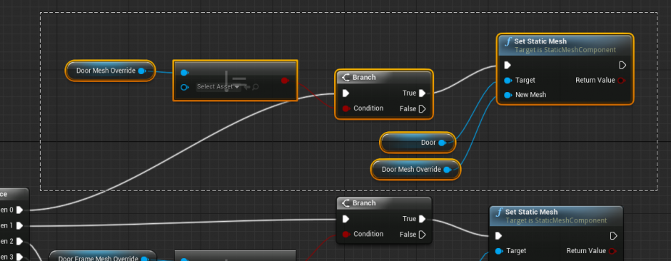
8. Ctrl-drag a copy of the
Door
component variable into the Event Graph. Drag a wire from the variable and create a
Set Static Mesh
node. Make a duplicate of the
Door Mesh Override
variable and plug it into the
New Mesh
input.
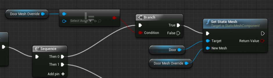
9. Repeat the process above to make a Set Static Mesh node that swaps out the mesh for the Door Frame component variable.
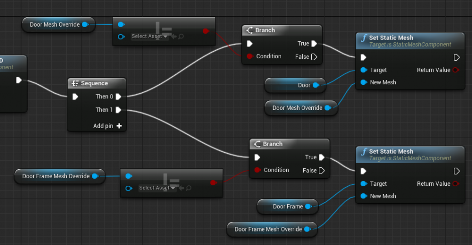
Your network should look like this when finished.
(Click for full size!)

11. Compile your Blueprint and save. If you have a copy in the viewport, look at the Details panel and find the new
Mesh & Materials Override
group. You can place other static meshes from the Content Browser into these variables, and the door will update accordingly.
Material Override
Double-click the Blueprint to open it in the Blueprint Editor and make sure that it has been added to the level for testing.
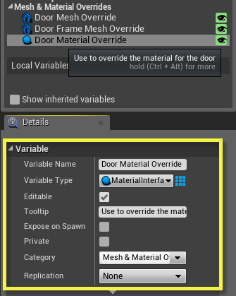
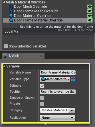
1. Create a new variable of type MaterialInterface named Door Material Override . Provide the following variable settings:
- Set the variable to be Editable .
- Set the tooltip to something describing that this variable will hold an override material for the door.
- Set the Custom Group Name to Mesh & Material Overrides .
2. Repeat the above step to create a new variable named
Door Frame Material Override
with an appropriate tooltip.
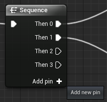
3. Take a look at the
Sequence
node. If it has only 2 output pins, click the
Add pin
button twice to give it a total of 4.
4. As with the meshes, we need to make sure that these variable contain some asset before we commence any execution. Create a Branch node for each variable, connecting them to each of the 2 open pins on the Sequence.
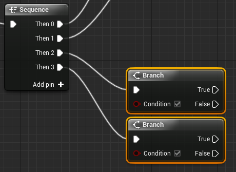
You may need to move around the other nodes to make room!
5. Ctrl-drag in the 2 new material override variables created above, then create a "Not Equal (object)" node for each variable, connected like so. These will drive the new Branches.
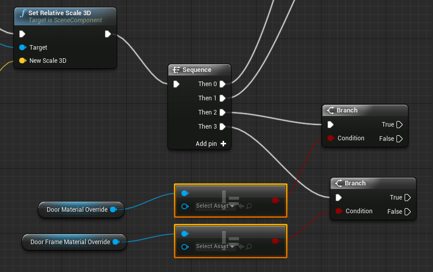
6. At this stage, we really only need to create the same type of network we produced for the mesh overrides. The only difference is that we use a
Set Material
node instead of a
Set Static Mesh
node to make the swap. Below you can see the final network, most of which can be created by simply duplicating the previous networks for overriding the meshes.

Leave the
Element Index
for both of the
Set Material
nodes set to
0
.
7. Compile and save your Blueprint. You may now specify material overrides for the meshes in the Blueprint. If left blank, there will be no change.
Chapter 3: Troubleshooting
The following is a list of common pitfalls one may run into when setting up mesh and material overrides for the door.
| Problem | Solution |
|---|---|
|
The Mesh and/or Material Override is not working.
I can place assets within the variables, but see no updates in the viewport. |
The problem is likely going to exist within your User Construction Script.
Remember that the Door/Material Override variables must be of the appropriate type. You must then make sure you're setting the right type of proprerty. If you're getting nothing at all, your best bet may be to carefully go back through the steps of the tutorial to see what you missed. |
| Material Instance Constants aren't working to override my materials. |
Make sure the variable type for your override materials is
Material Interface
.
You may have accidentally created a variable of type Material . That's going to be a problem, since you cannot place Material Instance Constant assets into that type of variable. Conversely, if you set the variable type to Material Instance Constant , you won't be able to use regular Materials. This is why in the tutorial we used the Material Interface type, which can take in both a regular Material and a Material Instance Constant. |
Organizing and Commenting
In this chapter we will look at how to go about separating your Blueprint network into easily identifiable sections. This serves a dual purpose:
- Making the network easier to "read" by chopping apart functionality into logical regions.
- Making it much easier to identify and fix problems when something doesn't work.
Generally speaking, the more modular your networks are - or, put another way, the more one applies the concept of "separation of concerns" - the easier it is to tell quickly where a problem lies and where exactly one must go to make changes.
We will also examine the process of applying comments to your Blueprint networks. Comments serve as an invaluable organizational tool, allowing you to explain an entire group of nodes wihtin a network, or even to put comments on individual nodes to explain their purpose. Just as when programming using actual code, using comments can make it much faster and easier for your work to be used and edited when in a team environment, or when having to walk away from a specific system for extended periods of time.
Custom Events and Organization
As a Blueprint network becomes more and more complex, it is a good idea to separate key parts of functionality into easily identifiable groups. Not only does this help by making it easier to see what each section of the network does, but it also makes it a much simpler task to insert additional functionality as you move forward.
In this case, we will separate out this behavior by using Custom Events.
1. Double-click the Blueprint to open it within the Blueprint Editor.
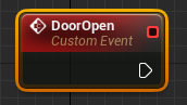
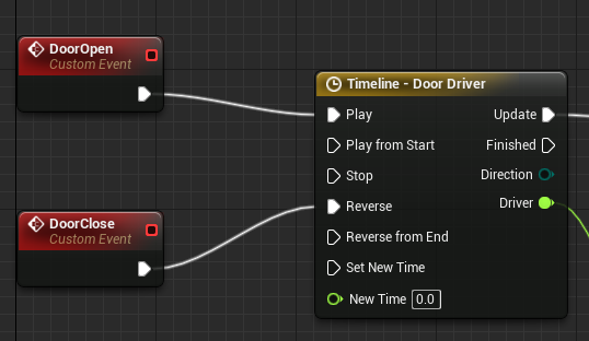
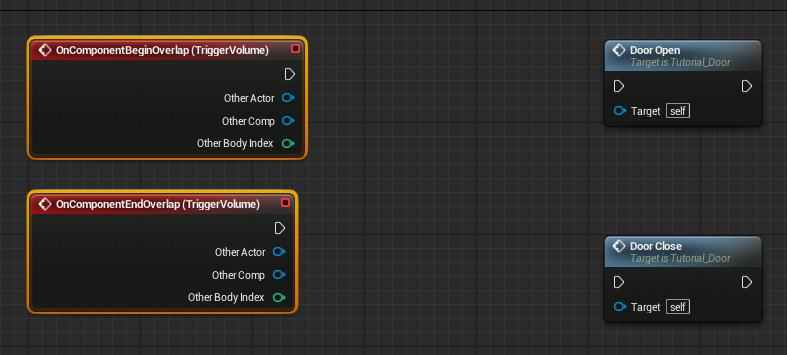
2. In the Event Graph, right-click somewhere near the OnComponentBeginOverlap (TriggerVolume) event in the Blueprint sequence and choose Add Custom Event . A new Custom Event will appear, prompting you to supply a name. Name this event DoorOpen .
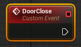
3. Next to the
OnComponentEndOverlap
event, create another Custom Event named
DoorClose
.
4. Disconnect the
OnComponentBeginOverlap
event and replace it with the
DoorOpen
Custom Event. Replace the
OnComponentEndOverlap
event with the
DoorClose
event.
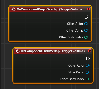
5. Move the
OnComponentBeginOverlap (TriggerVolume)
and
OnComponentEndOverlap (TriggerVolume)
events away from the main network.
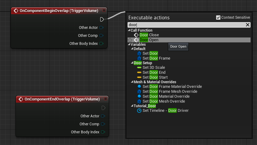
6. Drag a wire off the execution pin for
OnComponentBeginOverlap (TriggerVolume)
and release in empty space. Type "DoorOpen" and you will see a
DoorOpen
function appear. Create it. Repeat this process for
OnComponentEndOverlap (TriggerVolume)
and create a
DoorClose
function.
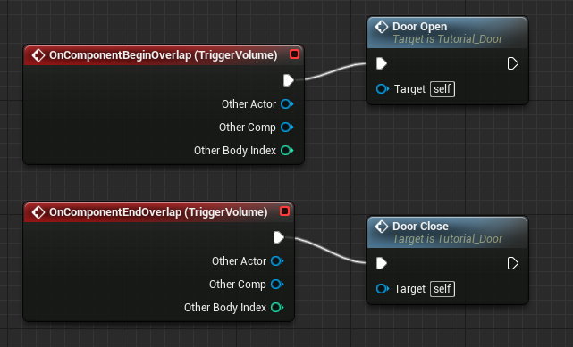
7. Compile, save, and test your door. By separating out your behavior like this, it will be much easier to see exactly what happens when a player touches the BoxComponent, as well as much easier to insert additional behavior later on.
Commenting
Commenting can be a lifesaver when it comes to more complex Blueprint networks. Should you be working on a team with multiple people, or ever have to walk away from a Blueprint only to have to come back and edit it later, having comments in place can make it much easier to follow along with what was already done. Comments can also make it clearer where additions should be made when trying to produce specific functionality.
1. Double-click the Blueprint to open it in the Blueprint Editor and make sure that it has been added to the level for testing.
2. Drag a selection box around the section of the network that handles door motion.
3. Press the
C
key to create a comment box. Alternatively, you may also right-click and choose
Create Comment from Selection
.
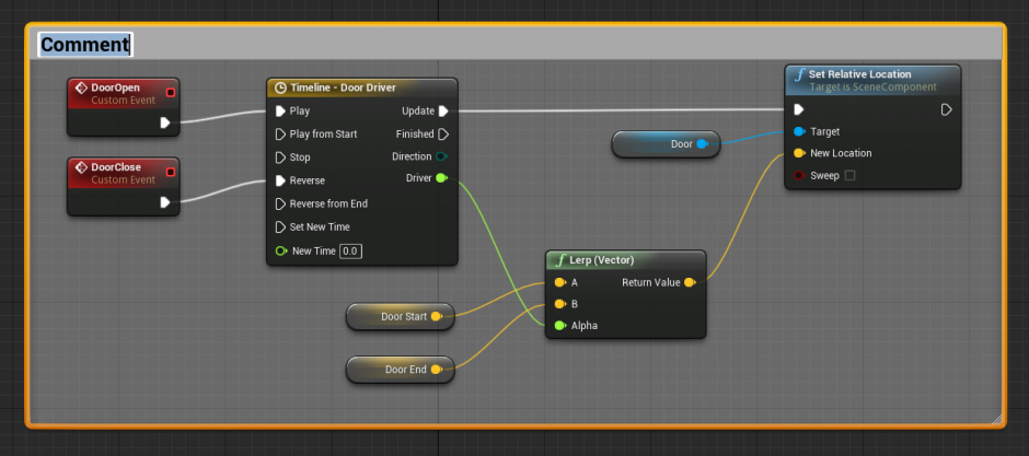
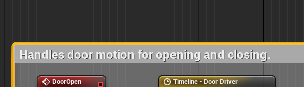
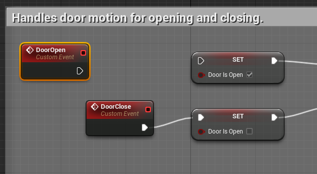
4. You can name a Comment as soon as it is created. However, this can also be done after the fact . Simply double-click on the comment and set it to something descriptive, such as, "Handles door motion for opening and closing."
5. Move the Comment box to a new location. Notice that all the nodes within it move as well.
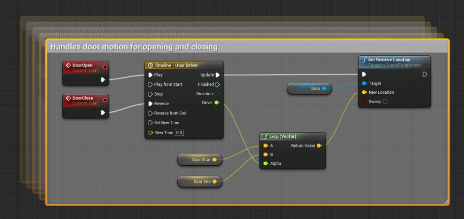
6. Compile and save your Blueprint.
Remember that unlike programming code, the visual nature of Blueprints - particularly how nodes can branch in many directions at once - means that it will often not be an easy task to glance at a network and see what it's supposed to be doing. Liberal use of comments can help make it a quick and easy task for you or anyone on your team to see what any part of a network is doing and where any edits or adjustments should take place.
Collapsing Nodes
Sometimes, for sake of organization, it can be a good idea to take a network of nodes and collapse them down into a single custom-named node. This creates a sub-graph of the nodes that were collapsed, leaving the main Graph much cleaner and in many cases, easier to read. In this example, we will apply this to the Construction Script to condense our mesh and material override networks down into singular nodes.
1. Double-click the Blueprint to open it in the Blueprint Editor and make sure that it has been added to the level for testing.
2. In the ConstructionScript tab, carefully select only those nodes that override the Door mesh. These should be connected to the Then 0 output pin of the Sequence node.
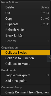
3. With those nodes selected, right-click on one of the selected nodes and choose
Collapse Nodes
from the context menu. A name entry box will appear; enter the name
Override Mesh - Door
. Press enter, and a new node will appear to replace the selections.
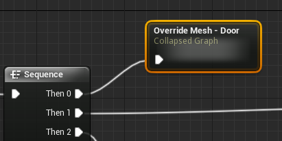
4. Repeat this process with the remaining networks that branch out of the
Sequence
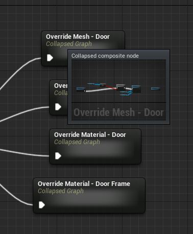
node. When finished, your network should look something like this:
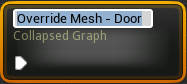
5. Mouse-over any of the collapsed nodes and notice the preview thumbnail that appears. This can give you a quick idea of the network within the collapsed node.
6. Double-click on any of the collapsed networks. This will allow you to "step inside" the node and see the network within.
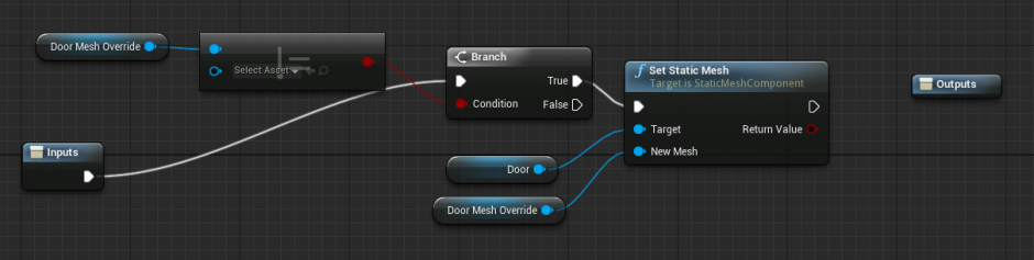
7. Notice the
Inputs
and
Outputs
nodes. These define the inputs and outputs that can be found on the collapsed node. By selecting either of these, you can go to the details panel and add further inputs and outputs.
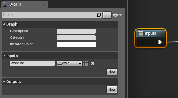
New
Input
and
Output
pins can be created by clicking the
New
button, and then adding a type and a name.
Unwanted Input and Output pins can be removed by clicking the X Remove button.
Notice that the Output node currently has no output in. This is because the final node in our selected network did not have an outgoing connection. Had we selected a series of nodes that were already connected to something else, then we would see an output connection of the appropriate type had been created automatically.
To add an execution pin rather than a variable data type, set the Type dropdown to exec . When doing so, you can set the name to a space if you want a single unnamed execution pin.
8. Compile and save your Blueprint.
Chapter 4: Troubleshooting
| Problem | Solution |
|---|---|
| I can't create a function before a Custom Event. Why is that? |
This is simply the nature of the workflow.
While you can create Custom Events with any name you like, there is no mechanism for creating the functions first. This prevents accidentally creating arbitrary functions which call non-existent events. |
| I can't seem to change the title of my Comment blocks. |
Make sure you're not looking for a "Comment" property, as one does not exist.
Simply double-click the comment title in the Graph. |
| My collapsed network does not have an output pin! |
This is to be expected, as long as you selected a series of nodes in which the final node was not outputting anything.
If you select a node that is outputting into another node, an output pin will be created and connected automatically. You can double-click any collapsed network and use the Details panel to modify the Tunnel Entrance and Tunnel Exit nodes to create your own inputs and outputs. |
Making a Useable Door
Chapter 5 takes a look at how we can modify our door so that a level designer has the option of making it a "useable" door. This means that instead of the door opening when a player enters the Box Component, the player will instead have to walk up to the door and press a "use" key on the keyboard.
Since this will be optional behavior, set up will require that we create a global Boolean variable that an LD can check in the Details panel, and the value of that variable will be used to branch behavior within our network. In short, the door will behave like so:
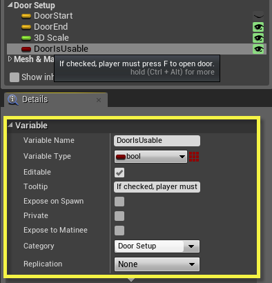
- Exposed global variable "Door Is Usable".
- If checked, the door must be used to open.
- If not checked, the door will open due to player proximity.
In order to make this system work, however, we will have to set up our Blueprint such that it can accept and process inputs from the user. This will require the implementation of a special Blueprint Interface.
Enabling Input
In order to make our door "usable" rather than merely proximity based, we have to set our Blueprint up in a special way so that it can receive inputs from the user.
This process in itself is very simple. However, from a useability standpoint, we have some changes to make in our network to make sure it works properly.
-
First, we will set up an editible variable (visible within the editor) that allows us to set the door as "usable."
- If this is checked, players will need to press a key to open and close the door.
- If not, the door will operate if the player enters or exits the box component. In this way, we set the stage for functionality options.
- If the door is set to be usable, then instead of opening the door when the player enters the BoxComponent, we will enable and disable the ability for inputs to be read. Those inputs will, in turn, open and close the door.
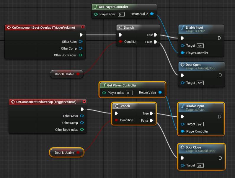
- We will create a special variable that will be used to monitor when the door is open and closed. This will keep the state of the door from falling out of sync, which could require the player to press their input an additional time, causing confusion and/or frustration.
In this tutorial, we will set up the system by which we enable inputs from the player.
1. Be sure to drag a copy of the Blueprint into the level for testing within PIE. Double-click the Blueprint to open it within the Blueprint Editor.
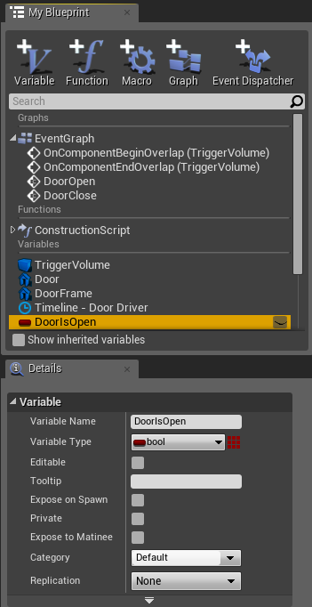
2. Create a new Boolean variable called "Door Is Usable." Give it the following properties:
3. Disconnect the
Door Open
and
Door Close
functions from the
OnComponentBeginOverlap
and
OnComponentEndOverlap
nodes. Move the function nodes away for the time being.
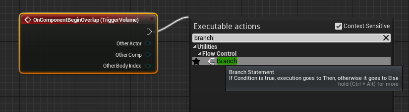
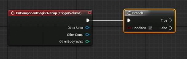
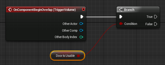
4. Drag a wire off the
OnComponentBeginOverlap
node, using the execution output pin, and create a new
Branch
node.
5. Ctrl-drag a copy of the
Door Is Usable
variable to the
Condition
input of the new
Branch
node.
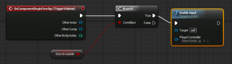
6. Drag a wire off the
True
output of the
Branch
node and create an
Enable Input
node. It will be easiest to start typing "Enable Input" in the search line.
7. Drag a wire backwards form the
Player Controller
input pin of the
Enable Input
node. Use the search line to create a
Get Player Controller
node.
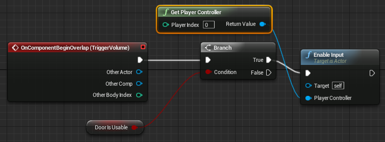
For sake of simplicity in this introductory tutorial, we are simply enabling and disabling input for Player 0, which is the player of a single player game. Things would get slightly more intricate if you needed multiplayer support, and is beyond the scope of this tutorial set.
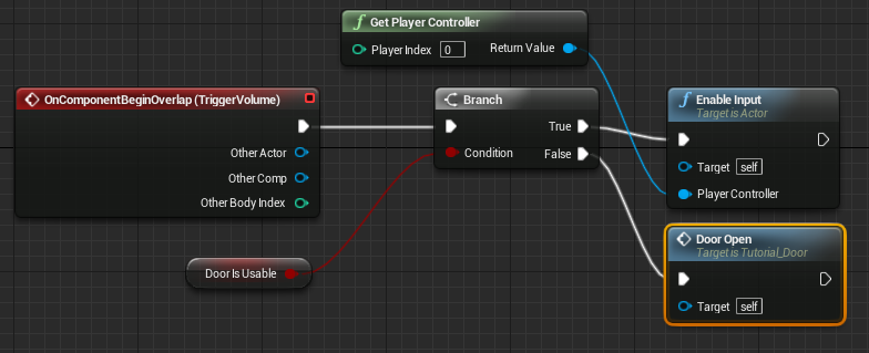
8. Drag a wire from the
False
output of the
Branch
node and create a
Door Open
function. This means that the door will open on proximity if the
Door Is Usable
variable is currently set to false.
9. Repeat the above steps for the
OnComponentEndOverlap
node, but swap the nodes connected to the
Branch
for a
Disable Input
node and a
Door Close
function, as shown.
10. Compile and save your Blueprint. At this time, there is no direct way to test our progress.
Key Events
In the previous tutorial, we set up our door to have the ability to accept inputs from the user. However, we now need to set up an event for the desired key press and tell the Blueprint script to do something with that input. To make sure things stay in sync with the current state of the door, we will start by creating a Boolean to track whether the door is open or closed.
1. Double-click the Blueprint to open it in the Blueprint Editor and make sure that it has been added to the level for testing.
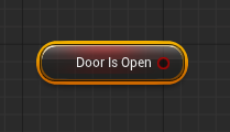
2. Create a new Boolean variable named Door Is Open . It requires no special settings. Ctrl-drag a Get variable node for Door Is Open into the Graph.
3. Right-click and create a new Input Event for the F key. These are found under
Input > Key Events
.
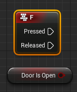
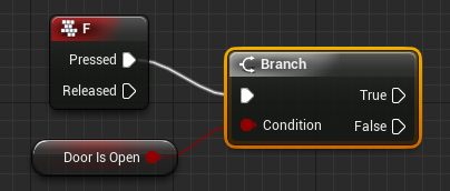
4. Drag a wire from the
Pressed
output of the
InputKey F
event and create a new
Branch
node. Connect the
Door Is Open
node to the
Condition
input.
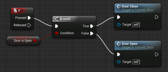
5. The next part is pretty straightforward from a logical standpoint. Create
Door Open
and
Door Closed
function and connect them to the
Branch
such that if the door is closed, we open it; and vice versa.
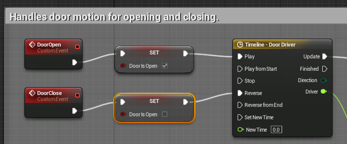
6. Our final step is to make sure that the
Door Is Open
variable gets updated appropriately.
Alt-drag
a copy of the variable into the graph and connect it in between the
Custom Event DoorOpen
and the
Timeline - Door Driver
nodes. Make sure to check its default value so that sets the variable properly. Repeat for the
Custom Event DoorClose
node as shown.
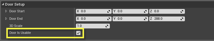
7. Compile and save your Blueprint. Notice the
Door Is Usable
checkbox in the Details panel when the door is selected in the viewport. When checked, you should have to press
F
to open the door. If unchcekd, the door should open when the player enters the BoxComponent.
Finalizing Use Controls
We need to set up a system such when we press the Use key (F in our case) the door will open and close. Although we could employ a FlipFlop node to handle this type of behavior, this may introduce the occasional bug if the state of the door and the use of the key ever get out of sync. In short, we could wind up telling a closed door to close again. Instead, we will create a new Boolean variable that stores the current state of the door, and use that to branch behavior of what happens when we press the F key. If the door is open, we'll close it. If it's closed, we'll open it.
1. Double-click the Blueprint to open it in the Blueprint Editor and make sure that it has been added to the level for testing.
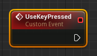
2. Create a Custom Event named UseKeyPressed .
The name UseKeyPressed was defined in an earlier tutorial in which we set up an InputComponent. If you have used another name to define the custom event for your use key, please use that instead. If necessary, go into the Components tab and double check the Action bindings on the InputController to make sure you're using the right name. Remember, if all else fails, just copy/paste it!
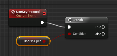
3. Create a new Branch node and connect it to the UseKeyPressed event. Right-click on its Condition input and choose Promote to Variable . Set the name of the new Boolean variable to DoorIsOpen .
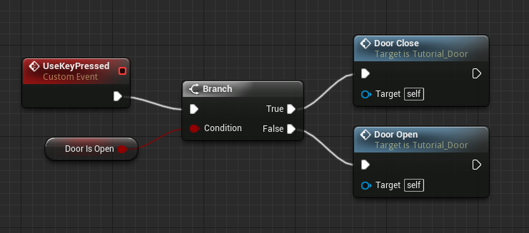
4. From the
True
output pin, create a new
DoorClose
function (or duplicate one from elsewhere in the graph). From the
False
output pin, create or duplicate a new DoorOpen function.
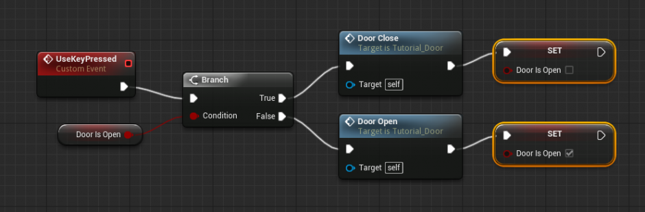
5. Alt-drag a copy of the DoorIsClosed Boolean variable (to create a set node) and connect one to each of the DoorOpen and DoorClosed functions. The DoorOpen version should set the variable to
True
(checked), while the DoorClosed version should set it to
False
(unchecked).
6. Compile and save your Blueprint. Test within the level.
- If the door's DoorIsUsable setting is checked (look in the Details panel), then the door will not open when approached.
- While within the BoxComponent, you should be able to press the Use key (F in our case) and thereby open and close the door.
- If you step away from the door's BoxComponent, you should no longer be able to open and close door.
- If the door's DoorIsUsable setting is UNchecked, then the door will simply work as a basic proximity door.
Chapter 5: Troubleshooting
| Problem | Solution | ||||||
|---|---|---|---|---|---|---|---|
| I press the F key and nothing happens! |
There are a few possible causes for this problem:
|
||||||
| I can press Use and open and close the door, no matter where I am in the level. |
The likeliest problem is that you're never firing an
Disable Input
node.
This means you're enabling inputs for the Blueprint door, but never relinquishing that ability. Make sure that your OnComponentEndOverlap event uses a Branch to check the Door Is Usable variable, and if it's set to True you should be executing an Disable Inputs node. |
Creating a Door Counter
Chapter 6 concludes this series of tutorials by demonstrating the creation of a special Blueprint whose sole job is to keep track of the number of times your door (or doors ) open. While not directly practical in and of itself, this does demonstrate how you can send data from one Blueprint to another.
To make this happen, we are going to need to create and implement a custom Blueprint Interface. This interface will include a customized function, allowing us to send the name of the new Counter Blueprint to our door, so that it can send info back, reporting each time it opens. The Counter will simply hold an integer that increments each time it receives a function call.
Of particular importance in this case is that the Counter will increment its stored value whenever it receives this call, no matter where it's coming from. This means we can have any number of doors in our level, and as long as each door is associated with the same Counter Blueprint Actor, the value will always represent the total number of times that any door has opened.
Custom Interface
As an exercise to help us see how Blueprints can talk to one another via Blueprint Interfaces, we are going to create a simple Blueprint that counts the number of times any of our level's doors open. This could potentially be used later for stat tracking, or even to cause some sort of event should enough doors be opened.
The system will work as follows:
- We will create an interface that serves to pass data between all parts of our door system.
- Our door will implement (or utilize) this interface.
- We will create a new custom transaction counter Blueprint that also implements this interface.
- Each time a door opens, it will call a custom increment function that is part of our interface.
- Because the counter also implements our interface, this same function will be called on the counter Blueprint, which will increment the transaction count and print the total to the screen.
This process is purely academic; generally, you will not create Blueprints designed specifically to log data to the screen. The purpose here is to show how, by way of an interface, we can call functions on other Blueprints.
Please be aware that this Tutorial assumes that you have now been working with with Blueprints at least a bit. As such, there will not be as much handholding throughout the steps.
1. Be sure to drag a copy of the Blueprint into the level for testing within PIE. Double-click the Blueprint to open it within the Blueprint Editor.
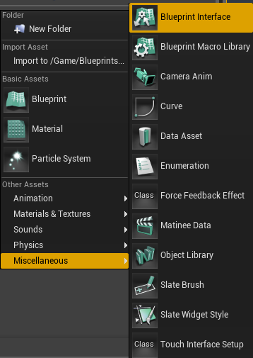
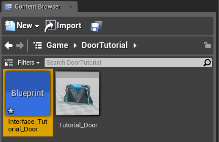
2. In the Content Browser, within the folder of your choice, create a new Blueprint Interface. Name it Interface_Tutorial_Door . Double-click it to open this interface in the Interface Editor.
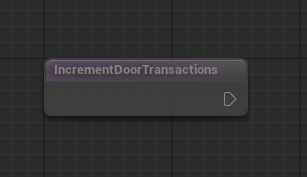
3. In the
My Blueprint
panel, click the
New Function
button and create a function named
"IncrementDoorTransactions."
This new function will appear in the
My Blueprint
list, and its graph will appear in the main editor view.
Notice that you cannot add nodes as you would in the Blueprint Editor. An interface only contains functions that have no functionality in and of themselves. Within any Blueprint that implements that interface, you may then use that function as a template, defining custom functionality from there.
4. Compile and save your Interface. We cannot yet test anything.
Making the Counter Blueprint
With the interface complete, we now have a means by which to make function calls from one Blueprint to another. In this tutorial, we will create a new non-rendering Blueprint whose only job is to keep track of the number of times any associated door has opened and print that to the screen.
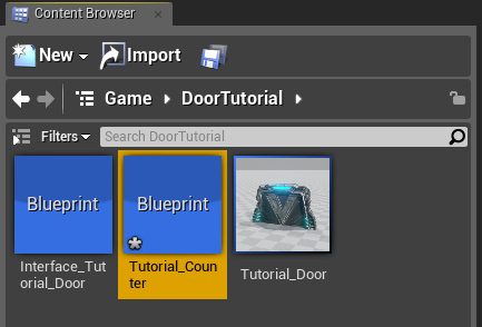
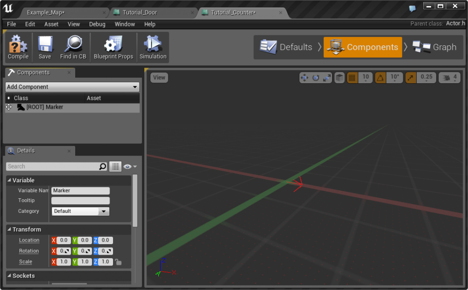
1. In the Content Browser, create a new Blueprint. Set the Parent Class to Actor. Name this Blueprint Tutorial_Counter and open it in the Blueprint Editor.
2. In the Components list
Components
Button in the Blueprint Editor toolbar), add a new
SpriteComponent
named
Marker
. This is only there to give us something to look at when the counter is placed in the level. We won't be using it for anything else. For newer UE4 v 4.12.5, the
SpriteComponent
is now called
BillboardComponent
.
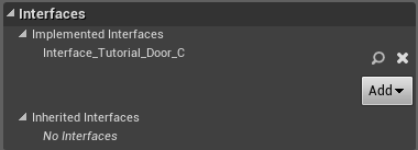
3. At the top of the Blueprint Editor, click the
Blueprint Props
Button which for newer UE4 version is called
Class Settings
. In the
Details
panel, look within the
Interfaces
category and click the
Add Interface
Button. Choose
Interface_Tutorial_Door
created in the previous tutorial. This will implement the interface, giving you access to all functions within that interface.
If you do not see your interface listed, make sure you saved the the interface!
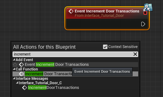
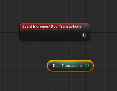
4. In the Event Graph, right-click and type "increment." You should see the IncrementDoorTransactions event appear within the list. Click it to create the event.
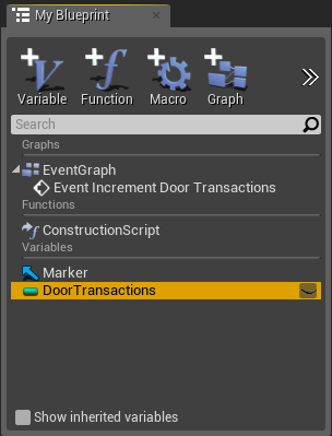
5. In the
My Blueprints
panel click the
Add Variable
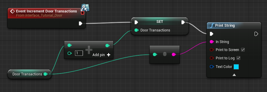
Button to create a new variable of type Int (integer) named DoorTransactions. This will hold the total door transactions for all doors associated with this Blueprint.
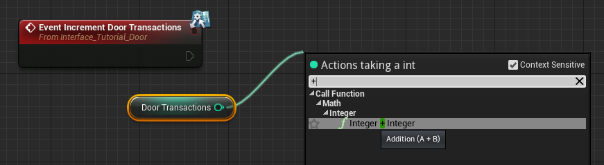
6. Ctrl-drag a copy of the
Door Transactions
variable into the Event Graph.
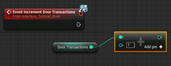
7. Drag a wire off the
Door Transactions
variable and type a
+
sign. You should see
+ (Integer)
appear in the list. Click to create one, and set the second input field to 1. This will add 1 to the current value of the
Door Transactions
variable.
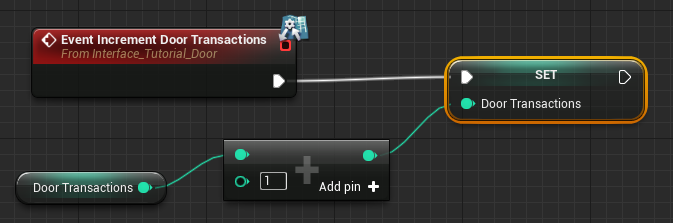
8. Alt-drag a copy of the
Door Transactions
variable into the Event Graph. This will create a
Set
node. Connect it to the event and then connect the result of the addition node to the Value input of the Set node.
9. Finally, create a
Print String
node. Wire it to take place after the Set variable node and connect the
Door Transactions
variable into the string input. Notice that a conversion node is automatically created.
10. Compile and save. At this point, the functionality for the complete. However, there is no way to test this until our door can be associated with the Blueprint.
Blueprint Actor Setup
We will now finish up the final steps in creating our Door Counter Blueprint, allowing us to track door transactions.
1. Open the Tutorial_Door Blueprint.
2. At the top of the Blueprint Editor, click the Blueprint Props Button which in newer UE4 v 4.12.5 is Class Settings button. In the Details panel, look within the Interfaces category, click the New Button and choose Interface_Tutorial_Door .

If you do not see your interface listed, make sure you saved the the interface!
3. Create a new variable of type Actor, named DoorCounter . Set this variable to global and give it a tooltip of, "This holds an associated transaction counter Blueprint." Set the Custom Group Name to Door Setup .
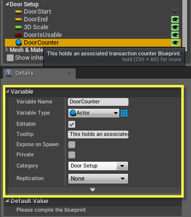
It is important to create an Actor variable, which can reference an actor that is placed within the level, as opposed to an Object variable, which cannot.
4. Locate the DoorOpen custom event, which should currently be connected to a Set Door Is Open node. Move the event away from the setter node and disconnect it.
5. Right-click in empty space (outside the Comment block!) and expand Interface Messages . You should see the name of your interface underneath. Expand this and you should see the IncrementDoorTransactions function. Click it to create the function.

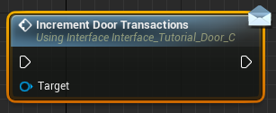
It is absolutely vital that you choose the version of the function listed under Interface Messages. There is also a version that lies under Functions, but it will only work locally. Visually, the only difference is that the Interface Message version has a light blue banner across the top.
6. Wire the new IncrementDoorTransactions node between the DoorOpen event and the Timeline.
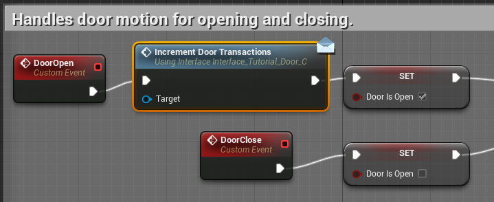
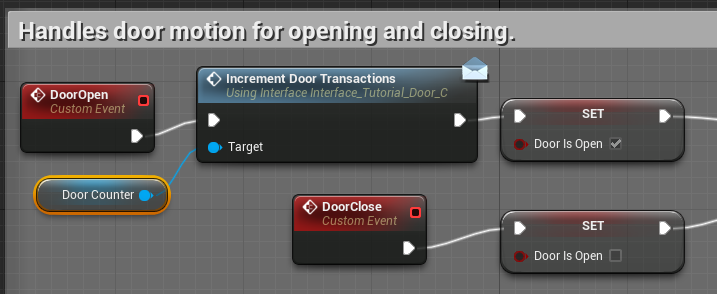
7. Ctrl-drag a copy of the DoorCounter variable into the Event Graph and connect it to the Target of the IncrementDoorTransactions function.
8. Compile and save.
9. To test, do the following:
- Drag a copy of the Counter Blueprint into the level.
- Select the door, which should already be placed within the level.
- Lock the Details panel, using the lock icon in the upper right of the panel.
- Select the Counter Blueprint from the Scene Outliner list.
- In the door's details, click the arrow next to the Door Counter setting. This will place a copy of that actor into the slot, associating the counter with that door.
- Optionally, create additional doors and associate them with this counter blueprint. No matter which door opens, the transactions should continue to increment.
Chapter 6: Troubleshooting
| Problem | Solution |
|---|---|
| I don't see my Blueprint Interface in the Interface list. |
Make sure you saved the Interface asset in the Content Browser.
Though rarely an issue, you should also try closing and re-opening your Blueprint in the Blueprint Editor. |
| I cannot connect my DoorCounter variable to the Target input on the IncrementDoorTransactions function. |
The likeliest problem is that you're using the wrong
version
of your function.
Each function has a local and non-local version. You want to make sure you're using the one listed under Interface Messages in the context menu. That's the only one that actually transmits by way of the interface to other Blueprints. |